Porcelain Insulator News
by Elton Gish, NIA #41
Reprinted from "INSULATORS - Crown Jewels of the Wire", April-May 1985, page 22
** NEW BOOK **
INSULATOR PATENTS, 1880-1960, by Jack H. Tod, 1985, softbound, 11" x 8-1/2", 130 pages, $20 plus
80 cents shipping.
This new book will be published this summer and is a must for every
collector, porcelain and glass alike. The book is a compilation of 695 insulator
patents represented on reference cards with a sketch of the insulator showing
the detail of the patent. There are six cards per page. If you have ever
searched through Official Patent Gazettes looking for a particular patent, you
can appreciate the thousands of thankless hours represented in this book from 80
years of patents; namely, 2,740,000+ letters patents and 177,000+ design patents
then making notes and sketches of each one that had anything to do with
insulators.
It is absolutely fascinating to see all these many designs of insulators.
Some are practical and others are of little use or too difficult to manufacture.
Can you believe 126 patents for self-tying insulators? The patents cover cleats,
knobs, both glass and porcelain pin types, non-pin types, wall tubes, tie-wire
clips, shields, pegs and pins, sleeves, suspension types and many other categories.
Literally every patent pertaining to the insulator hobby is illustrated in this
superb book with patent number, date and notes on each.
No one but Jack would have devoted so much time and energy to put together
this one-of-a-kind reference.
NOTE: There was a misprint in the December 1984 issue of CJ on page 24 in the
third paragraph from the bottom. It should read: "...and then a tapered
mandrel...". Obviously a threaded mandrel cannot be pushed into a threaded
hole without a little magic.
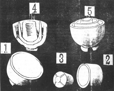
The following is a reprint from the April 5, 1902 issue of Electrical World
and Engineer, page 615 that I thought may be of interest. Note the grooves in
the center section (No. 3) to provide a channel for the glaze to flow and fill
the gap between the sections. There also are grooves in the second section. One
can be seen on the right-hand portion of No. 2 but probably will not show up
when the Xeroxed photo is reproduced here.
Boch's "Glaze-Filled" Insulator.
In the controversy between the advocates of porcelain and glass insulators
for high tension transmission lines, it is conceded for porcelain that it has
the advantage in respect to mechanical strength. The difficulty has been to make
high voltage insulators of porcelain uniformly free from flaws. When that has
been accomplished there can be little doubt that glass insulators can no longer
claim superiority in insulating quality over porcelain ones.
R. Thomas &
Sons' Company, of East Liverpool, Ohio, claim that their manager, Mr. J. W.
Boch, has accomplished the task of producing a flawless porcelain insulator of
superior insulating qualities as well as of great mechanical strength in his
"glaze-filled" insulator. This insulator has gone into practical use
during the past few years on high tension lines all over the country and has met
with marked success. It is of interest therefore to know how this insulator is
made, especially as Mr. Boch's patent has been recently sustained by the United
States Circuit Court.
Mr. Boch's invention is primarily based upon the fact
known ever since pottery was invented, that a thin piece of clay will mould and
vitrify better than a thick one. For this reason Mr. Boch builds up his
insulator out of two or more shells nested together. In the photo-engraving are
shown separately at 1, 2 and 3, the three shells of which Mr. Boch makes up his
triple petticoat insulator. The inner piece 3 is moulded with a suitable
threaded socket (see Fig. 4) for the usual pin. The outer shell 1 is provided
with the usual notched head for the conductor and like the intermediate part 2
is made bowl-shaped, so that the three are relatively thin shells, to he nested
into each other.
In the practice usually followed by R. Thomas & Sons'
Company, in making these insulators, these separately-molded parts are first
dried out separately, preferably in an oven or kiln in the usual manner of drying clay
articles by the process known as "biscuit firing". The
separate parts are then coated with glaze all over, as by dipping into liquid
glazing material, and they are then fitted into each other and stood upside
down, that is, petticoats uppermost, as in the position shown at 5. Extra
glazing material is supplied at the joints, that is, in the annular channels
between the petticoats.
The parts thus put together and supplied with extra
glaze at the joints are now put in the sagger with the petticoats of the
insulator uppermost and placed in a kiln, in which under great heat the clay
shrinks and becomes vitrified as usual and the glazing material melts and
becomes of a glass-like character, flowing down into and filling all the spaces
between the parts, such spaces either being there by lack of correct fit of the
parts or arising during the shrinkage of the clay by the vitrification. The separately
molded shells are thus welded together by seams of glass-like glaze, and this
welding has been found to be of so tenacious a character that the insulators can
be broken less easily along the lines of the "glaze-filled" seams than
elsewhere. The completed insulator is shown at 5, while at 4 is shown one cut in
two. This section clearly illustrates the three shells and the intermediate
"glaze-fillings," which, needless to say, add to the electrical
insulating qualities of the insulator as well as its mechanical strength.
|

)